大多数人听到“JPEG解码”时,通常会觉得这是很困难的事,需要很强的处理能力以及复杂的数学运算,并认为在相对便宜且速度较慢的8位处理器平台(比如Arduino)上是不可能实现的,或者说至少是不切实际的。在本文中,我们将学习如何使用基于Arduino控制的相机拍摄JPEG照片,以及如何将照片转换成像素点矩阵,并将所有像素通过串行端口传输到我们的PC端或者任何我们想要的平台上!
硬件
- • Arduino Mega
- • VC0706 串口摄像头
- • 带SPI接口的SD卡模块
软件
- • Arduino IDE
- • Processing (3.3.2 或更高版本)
- • Adafruit VC0706 库 (可从 GitHub上获取)
- • Bodmer 的 JPEGDecoder 库 (同样可从 GitHub上获取)
虽然说上面描述的内容是完全可以实现的,但是仍然有必要解释一下为什么我们在解码JPEG照片时会遇到麻烦。毕竟,在上面的硬件要求中列有一个SD模块,您会问:“我们直接把照片以photo.jpeg 的格式存储到SD卡里不就行了吗?”当然,这确实是整个过程中的重要一步,但是现在请从不同的角度来考虑这个问题:如果我们想通过速度慢、有些不稳定的连接来发送照片怎么办?如果我们只是把JPEG照片分割成不同的包并通过慢速连接发送,那么就有部分数据损坏或丢失的风险。发生这种情况时,我们很可能无法用损坏的数据还原原始数据。
但是,当我们将JPEG解码为位图,然后发送实际像素时,不会有任何风险。如果某些数据在传输的过程中损坏或丢失,我们仍然可以获取整张图像,只有数据损坏的地方会出现失色,错位或像素丢失的情况。当然,它与我们的原始图像并不相同,但是仍然包含了大多数原始信息,并且仍然是“可读的”。既然已经知道了为什么要这样做,接下来让我们看一下如何实施这种方法。
拍摄照片
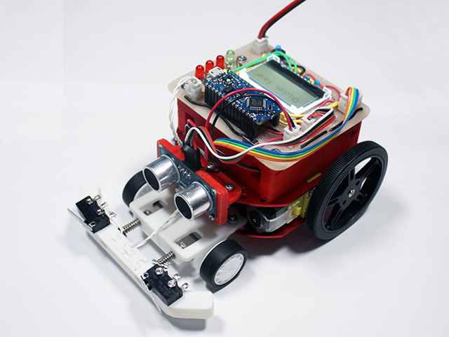
在开始解码JPEG照片之前,首先我们需要拍摄照片。我们最终的目标是拍摄一张照片,将照片存储到SD卡中,然后发送到某个地方。那我们按照这个思路先从一个简单的设置开始吧。

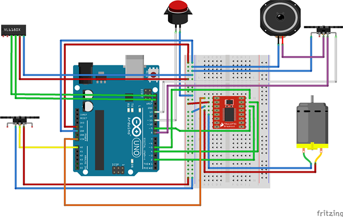
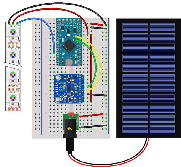
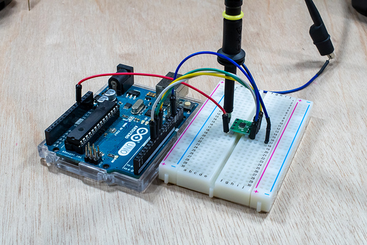
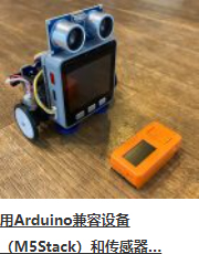
图1:可以使用Arduino拍摄和存储照片的设置
因为我们需要大量的RAM来对照片进行解码,所以我们将使用Arduino Mega。此外,Mega上还有一个额外的有利设计:有四个单独的硬件串行端口,这样我们就可以使用Serial1端口与相机进行通信,并使用Serial端口与PC进行通信。
您可能已经注意到了,相机RX线上有一个简单的电阻分压器。这是因为VC0706芯片的逻辑电平为3.3V(即使电源电压为5V),但Arduino Mega的逻辑电平为5V。所以在这里有个善意忠告:当将5V的Arduino和3.3V模块进行接合时,在RX线上始终至少使用一个分压器。这比换一个新的模块要快得多。SD卡读卡器通过SPI接口直接连接。
既然硬件已经设置好了,那我们就需要开始解决代码部分了。标准Arduino IDE安装已经包含了用于SD卡的库,因此我们从列表中对SD卡进行查看即可。
我们需要控制的另一个设备是VC0706摄像头。控制过程相对简单,我们只需要使用串行线发送一些指令,然后通过同一条线接收JPEG照片即可。我们可以编写一个库来执行此操作,但是因为这一步我们不需要考虑整体草图的大小,所以我们将使用Adafruit开发的一个VC0706库。为了拍摄照片并保存到SD卡上,我们将使用以下代码,代码是该库随附的经过轻微修改的Snapshot示例。
// Include all the libraries
#include <Adafruit_VC0706.h>
#include <SPI.h>
#include <SD.h>

// Define Slave Select pin
#define SD_CS  53

// Create an instance of Adafruit_VC0706 class
// We will use Serial1 for communication with the camera
Adafruit_VC0706 cam = Adafruit_VC0706(&Serial1);

void setup() {
  // Begin Serial port for communication with PC
  Serial.begin(115200);

  // Start the SD
  if(!SD.begin(SD_CS)) {
    // If the SD can't be started, loop forever
    Serial.println("SD failed or not present!");
    while(1);
  }

  // Start the camera
  if(!cam.begin()) {
    // If the camera can't be started, loop forever
    Serial.println("Camera failed or not present!");
    while(1);
  }

  // Set the image size to 640x480
  cam.setImageSize(VC0706_640x480);
}

void loop() {
  Serial.print("Taking picture in 3 seconds ... ");
  delay(3000);

  // Take a picture
  if(cam.takePicture()) {
    Serial.println("done!");
  } else {
    Serial.println("failed!");
  }

  // Create a name for the new file in the format IMAGExy.JPG
  char filename[13];
  strcpy(filename, "IMAGE00.JPG");
  for(int i = 0; i < 100; i++) {
    filename[5] = '0' + i/10;
    filename[6] = '0' + i%10;
    if(!SD.exists(filename)) {
      break;
    }
  }

  // Create a file with the name we created above and open it
  File imgFile = SD.open(filename, FILE_WRITE);

  // Get the size of the image
  uint16_t jpglen = cam.frameLength();
  Serial.print("Writing ");
  Serial.print(jpglen, DEC);
  Serial.print(" bytes into ");
  Serial.print(filename);
  Serial.print(" ... ");

  // Read all the image data
  while(jpglen > 0) {
    // Load the JPEG-encoded image data from the camera into a buffer
    uint8_t *buff;
    uint8_t bytesToRead = min(32, jpglen);
    buff = cam.readPicture(bytesToRead);

    // Write the image data to the file
    imgFile.write(buff, bytesToRead);
    jpglen -= bytesToRead;
  }

  // Safely close the file
  imgFile.close();

  Serial.println("done!");
  delay(3000);
}
现在,Arduino将每10秒左右拍摄一张照片,直到SD卡上的空间用完为止。但是,由于照片通常约为48kB,并且我目前使用的是2GB的SD卡,因此足够容纳超过43000张的照片。理论上来说我们不需要那么多的照片。但是既然已经拍摄了一些照片,我们现在可以继续进行下一个有趣环节了:将它们从JPEG压缩后的难以管理的杂乱数据变成简单的像素阵列!
解码和发送照片
在开始解码前,让我们快速地看一下图片数据在JPEG文件中究竟是如何存储的。如果您对这部分不太感兴趣,可以跳过下面三段内容。如果您确切地对图形和压缩方面的知识了解一二(不像我这样),您也可以跳过这一部分。以下内容进行了一定程度的简化。
对任何类型的图片数据进行存储时,有两种基本方法:无损和有损压缩。两者的区别很明显:当使用无损压缩(例如PNG)对图像进行编码时,处理之后图像的每个像素都与开始时完全相同。这非常适合于诸如计算机图形学之类的工作,但是不幸的是,这是以增加文件大小为代价的。另一方面,对于像JPEG这样的有损压缩,我们丢失了一些细节,但是生成的文件大小要小得多。
JPEG压缩方式在理解上可能会有点困难,因为会涉及到一些“离散余弦变换”,不过主要原理实际上是非常简单的。首先,将图片从RGB颜色空间转换为YCbCr。我们都知道RGB颜色空间—它存储了红色(R)、绿色(G)和蓝色(B)的颜色值。YCbCr有很大的不同—它使用亮度(Y—基本是原始图像的灰度图),蓝色差分量(Cb—图片中的“蓝色”)和红色差分量(Cr—图片中的“红色”)。

图2:JPEG照片以及其分离出的色差分量。左上角为原始图像,左下角为Y分量,右上角为Cb分量,右下角为Cr分量
JPEG减小文件大小的方法实际上与人眼处理颜色的方式密切相关。看一下上图中的Y、Cb和Cr分量图。哪一个看起来更像是原始图片?是的,灰度图!这是因为人眼对亮度的敏感度要比对其它两个分量的敏感度高得多。JPEG压缩就非常聪明地利用了这一点,在保留原始Y分量的同时减少Cb和Cr分量中的信息量。如此一来,生成的图片就比原始文件小得多,并且由于大多数压缩信息都位于人眼不太敏感的分量中,因此与未压缩的图片相比,您几乎看不到压缩图片的区别。
现在,让我们开始运行真正实现将JPEG转换为像素阵列的代码吧。幸运的是,有一个库可以做到这一点—Bodmer的JPEGDecoder(可在GitHub上获得),该库基于Rich Geldreich(也可在GitHub)上获取)提供的出色的picojpeg库。虽然最初编写JPEGDecoder的目的是在TFT显示器上显示图像,但是将其进行一些细微调整后就可以用于我们的工作了。
该库的使用非常简单:我们输入JPEG文件,然后该库就会开始产生像素阵列—所谓的最小编码单位,或简称为MCU。MCU是一个16×8的像素块。库中的函数将以16位颜色值的形式返回每个像素点的颜色值。高5位是红色值,中6位是绿色值,低5位是蓝色值。现在,我们可以通过任何通信通道来发送这些值。我将使用串行端口,以便之后可以更容易地接收数据。下面的Arduino草图对一张图像进行了解码,然后发送了MCU中每个像素点的16位RGB值,并对图像文件中的所有MCU重复该操作。
// Include the library
#include <JPEGDecoder.h>

// Define Slave Select pin
#define SD_CS  53

void setup() {
  // Set pin 13 to output, otherwise SPI might hang
  pinMode(13, OUTPUT);

  // Begin Serial port for communication with PC
  Serial.begin(115200);

  // Start the SD
  if(!SD.begin(SD_CS)) {
    // If the SD can't be started, loop forever
    Serial.println("SD failed or not present!");
    while(1);
  }

  // Open the root directory
  File root = SD.open("/");

  // Wait for the PC to signal
  while(!Serial.available());

  // Send all files on the SD card
  while(true) {
    // Open the next file
    File jpgFile = root.openNextFile();

    // We have sent all files
    if(!jpgFile) {
      break;
    }

    // Decode the JPEG file
    JpegDec.decodeSdFile(jpgFile);

    // Create a buffer for the packet
    char dataBuff[240];

    // Fill the buffer with zeros
    initBuff(dataBuff);

    // Create a header packet with info about the image
    String header = "$ITHDR,";
    header += JpegDec.width;
    header += ",";
    header += JpegDec.height;
    header += ",";
    header += JpegDec.MCUSPerRow;
    header += ",";
    header += JpegDec.MCUSPerCol;
    header += ",";
    header += jpgFile.name();
    header += ",";
    header.toCharArray(dataBuff, 240);

    // Send the header packet
    for(int j=0; j<240; j++) {
      Serial.write(dataBuff[j]);
    }

    // Pointer to the current pixel
    uint16_t *pImg;

    // Color of the current pixel
    uint16_t color;

    // Create a data packet with the actual pixel colors
    strcpy(dataBuff, "$ITDAT");
    uint8_t i = 6;

    // Repeat for all MCUs in the image
    while(JpegDec.read()) {
      // Save pointer the current pixel
      pImg = JpegDec.pImage;

      // Get the coordinates of the MCU we are currently processing
      int mcuXCoord = JpegDec.MCUx;
      int mcuYCoord = JpegDec.MCUy;

      // Get the number of pixels in the current MCU
      uint32_t mcuPixels = JpegDec.MCUWidth * JpegDec.MCUHeight;

      // Repeat for all pixels in the current MCU
      while(mcuPixels--) {
        // Read the color of the pixel as 16-bit integer
        color = *pImg++;

        // Split it into two 8-bit integers
        dataBuff[i] = color >> 8;
        dataBuff[i+1] = color;
        i += 2;

        // If the packet is full, send it
        if(i == 240) {
          for(int j=0; j<240; j++) {
            Serial.write(dataBuff[j]);
          }
          i = 6;
        }

        // If we reach the end of the image, send a packet
        if((mcuXCoord == JpegDec.MCUSPerRow - 1) &&
          (mcuYCoord == JpegDec.MCUSPerCol - 1) &&
          (mcuPixels == 1)) {

          // Send the pixel values
          for(int j=0; j<i; j++) {
            Serial.write(dataBuff[j]);
          }

          // Fill the rest of the packet with zeros
          for(int k=i; k<240; k++) {
            Serial.write(0);
          }
        }
      }
    }
  }

  // Safely close the root directory
  root.close();
}

// Function to fill the packet buffer with zeros
void initBuff(char* buff) {
  for(int i = 0; i < 240; i++) {
    buff[i] = 0;
  }
}

void loop() {
  // Nothing here
  // We don't need to send the same images over and over again
}
注释中已经对大多数代码进行了解释,但是我还是需要对代码结构中的“包”进行一些说明。为了使数据传输更加有序,所有内容都以包的形式传输,最大长度为240字节。包有两种可能的类型:
- 1.头包:此包以字符串“$ITHDR”开头,并且包含我们将要发送的图片的基本信息:以像素为单位的高度和宽度,行和列前的MCU数量,最后是原始文件名。对于我们要发送的每个图像,都会相应发送一个头包。
- 2.数据包:该包以“$ITDAT”开头,并包含所有颜色数据。该数据包中的每两个字节代表一个16位像素值。
乍一看,包的长度似乎是随机的。但是为什么恰好是240个字节?为什么不是256个,使我们可以在每个包中发送两个MCU呢?这是另一个我们日后将会解决的谜团,但是我们可以保证, 数字240不会有任何随机性。这里有个小提示:如果包中有256个字节的数据,我们要在哪里存储源地址和目标地址呢?
现在,我们有了一个可以解码和发送图片文件的代码,但是仍然缺少一个核心功能:目前为止,并没有可以响应这些数据的另一端口。这意味着是时候再次启用Processing了!
接收图片
我在Arduino六足机器人第三部分:远程控制中曾介绍过一些有关Processing的内容,用其编写了一个应用程序,通过该应用程序我们能够轻松控制六足机器人。简单回顾一下:Processing是一种基于Java的语言,主要用于绘图工作。因此它非常适用于我们现在要做的像素显示的工作!该程序就是用Processing实现的。
// Import the library
import processing.serial.*;

Serial port;

void setup() {
  // Set the default window size to 200 by 200 pixels
  size(200, 200);

  // Set the background to grey
  background(#888888);

  // Set as high framerate as we can
  frameRate(1000000);

  // Start the COM port communication
  // You will have to replace "COM30" with the Arduino COM port number
  port = new Serial(this, "COM30", 115200);

  // Read 240 bytes at a time
  port.buffer(240);
}

// String to save the trimmed input
String trimmed;

// Buffer to save data incoming from Serial port
byte[] byteBuffer = new byte[240];

// The coordinate variables
int x, y, mcuX, mcuY;

// A variable to measure how long it takes to receive the image
long startTime;

// A variable to save the current time
long currentTime;

// Flag to signal end of transmission
boolean received = false;

// Flag to signal reception of header packet
boolean headerRead = false;

// The color of the current pixel
int inColor, r, g, b;

// Image information variables
int jpegWidth, jpegHeight, jpegMCUSPerRow, jpegMCUSPerCol, mcuWidth, mcuHeight, mcuPixels;

// This function will be called every time any key is pressed
void keyPressed() {
  // Send something to Arduino to signal the start
  port.write('s');
}

// This function will be called every time the Serial port receives 240 bytes
void serialEvent(Serial port) {
  // Read the data into buffer
  port.readBytes(byteBuffer);

  // Make a String out of the buffer
  String inString = new String(byteBuffer);

  // Detect the packet type
  if(inString.indexOf("$ITHDR") == 0) {
    // Header packet

    // Remove all whitespace characters
    trimmed = inString.trim();

    // Split the header by comma
    String[] list = split(trimmed, ',');

    // Check for completeness
    if(list.length != 7) {
      println("Incomplete header, terminated");
      while(true);
    } else {
      // Parse the image information
      jpegWidth = Integer.parseInt(list[1]);
      jpegHeight = Integer.parseInt(list[2]);
      jpegMCUSPerRow = Integer.parseInt(list[3]);
      jpegMCUSPerCol = Integer.parseInt(list[4]);

      // Print the info to console
      println("Filename: " + list[5]);
      println("Parsed JPEG width: " + jpegWidth);
      println("Parsed JPEG height: " + jpegHeight);
      println("Parsed JPEG MCUs/row: " + jpegMCUSPerRow);
      println("Parsed JPEG MCUs/column: " + jpegMCUSPerCol);

      // Start the timer
      startTime = millis();
    }

    // Set the window size according to the received information
    surface.setSize(jpegWidth, jpegHeight);

    // Get the MCU information
    mcuWidth = jpegWidth / jpegMCUSPerRow;
    mcuHeight = jpegHeight / jpegMCUSPerCol;
    mcuPixels = mcuWidth * mcuHeight;

  } else if(inString.indexOf("$ITDAT") == 0) {
    // Data packet

    // Repeat for every two bytes received
    for(int i = 6; i < 240; i += 2) {
      // Combine two 8-bit values into a single 16-bit color
      inColor = ((byteBuffer[i] & 0xFF) << 8) | (byteBuffer[i+1] & 0xFF);

      // Convert 16-bit color into RGB values
      r = ((inColor & 0xF800) >> 11) * 8;
      g = ((inColor & 0x07E0) >> 5) * 4;
      b = ((inColor & 0x001F) >> 0) * 8;

      // Paint the current pixel with that color
      set(x + mcuWidth*mcuX, y + mcuHeight*mcuY, color(r, g, b));

      // Move onto the next pixel
      x++;

      if(x == mcuWidth) {
        // MCU row is complete, move onto the next one
        x = 0;
        y++;
      }

      if(y == mcuHeight) {
        // MCU is complete, move onto the next one
        x = 0;
        y = 0;
        mcuX++;
      }

      if(mcuX == jpegMCUSPerRow) {
        // Line of MCUs is complete, move onto the next one
        x = 0;
        y = 0;
        mcuX = 0;
        mcuY++;
      }

      if(mcuY == jpegMCUSPerCol) {
        // The entire image is complete
        received = true;
      }
    }
  }
}

void draw() {
  // If we received a full image, start the whole process again
  if(received) {

    // Reset coordinates
    x = 0;
    y = 0;
    mcuX = 0;
    mcuY = 0;

    // Reset the flag
    received = false;

    // Measure how long the whole thing took
    long timeTook = millis() - startTime;
    println("Image receiving took: " + timeTook + " ms");
    println();
  }
}
当您在连接Arduino之后运行该程序,然后按下键盘上的任意键时,您(希望)会看到暗淡、单一的灰色背景逐渐被最初存储在SD卡上的图像所取代。由于替换是逐像素进行的,因此整个过程具有一种老式拨号调制解调器的加载图像风格!

图3:使用Processing应用程序将照片从Arduino加载到PC
虽然我们以相当高的波特率(准确值为115200)运行串行端口,接收一张图像也需要大约60秒。我们可以用它来计算实际的传输速度。
原始图像宽640像素,高480像素,总计307200像素。每个像素都由2字节的颜色值来表示,总共要传输614400个字节(即600KB)。那么我们的最终速度约为10kB/s。对于我们制定的“协议”来说,这并不算很糟糕,不是吗?此外,它还向您展示了为什么图像压缩如此有用。原始JPEG文件只有48kB左右,而解码后的位图则需要600kB。如果我们要传输JPEG文件,即使使用非常简单的“协议”,也可以在5秒之内完成传输。当然,万一传输失败,我们将可能无法追回任何数据—这种情况现在已经不会发生了。
结论
最后,我们证实了本文开头所说的:在Arduino上处理图像是可能的,并且在某些情况下可能会更有优势。现在,我们可以使用串行相机拍摄照片,对其进行解码,通过串行端口发送,然后在另一端接收了!可以将本文作为您在Arduino上进行图像处理的入门简介。
像往常一样,有很多方面都可以进一步改善。一个需要添加的主要功能可能是使用AES对我们的消息进行加密,这一点很容易实现(即使在Arduino上)。在Arduino上,安全性通常会被忽视,这是很危险的,因此在下一个项目中我们可能会将重点更多地放在安全性上。
感谢您阅读本文!请继续关注我们的其他有趣项目!也许有些项目将会使用到我们在本项目中所学到的所有内容!
Jan Gromes
Jan目前就读于布尔诺理工大学电气工程专业,拥有多年Arduino和其他微控制器专业经验,尤其对机器人系统的机械设计感兴趣。